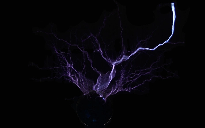
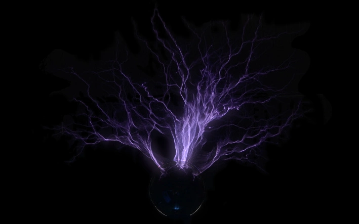
Tesla coils are among the more exciting physics demonstrations. The presented experiments generally feature wireless energy transfer or sparks of varying length. Because the generated voltage alternates at a high frequency, sparks generally discharge into the air. This effect is often referred to as streamer discharge. I have built many tesla coils over the years. This article will only describe some of my builds and focus on the historic spark gap controlled design.
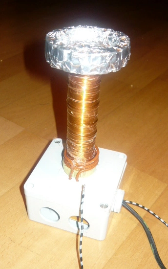
Let's go for a short trip on memory lane by looking at the first Tesla coil I ever built (3rd one) back when I was in middle school. It used a blocking oscillator to resonantly drive a small mains transformer. This generated roughly 3kV at a few kilohertz. The transformer output was rectified to feed the classic spark gap tesla coil design. Because the resonant circuits were not matched at all, this build could be more accurately described as an impulse transformer.
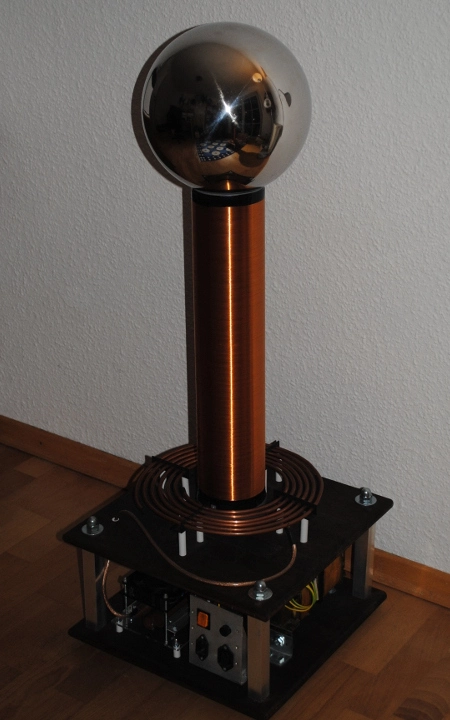
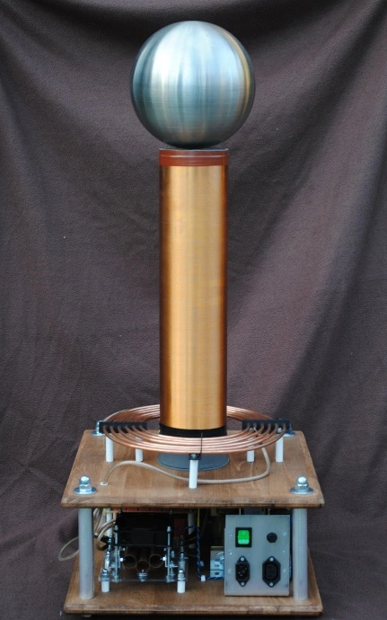
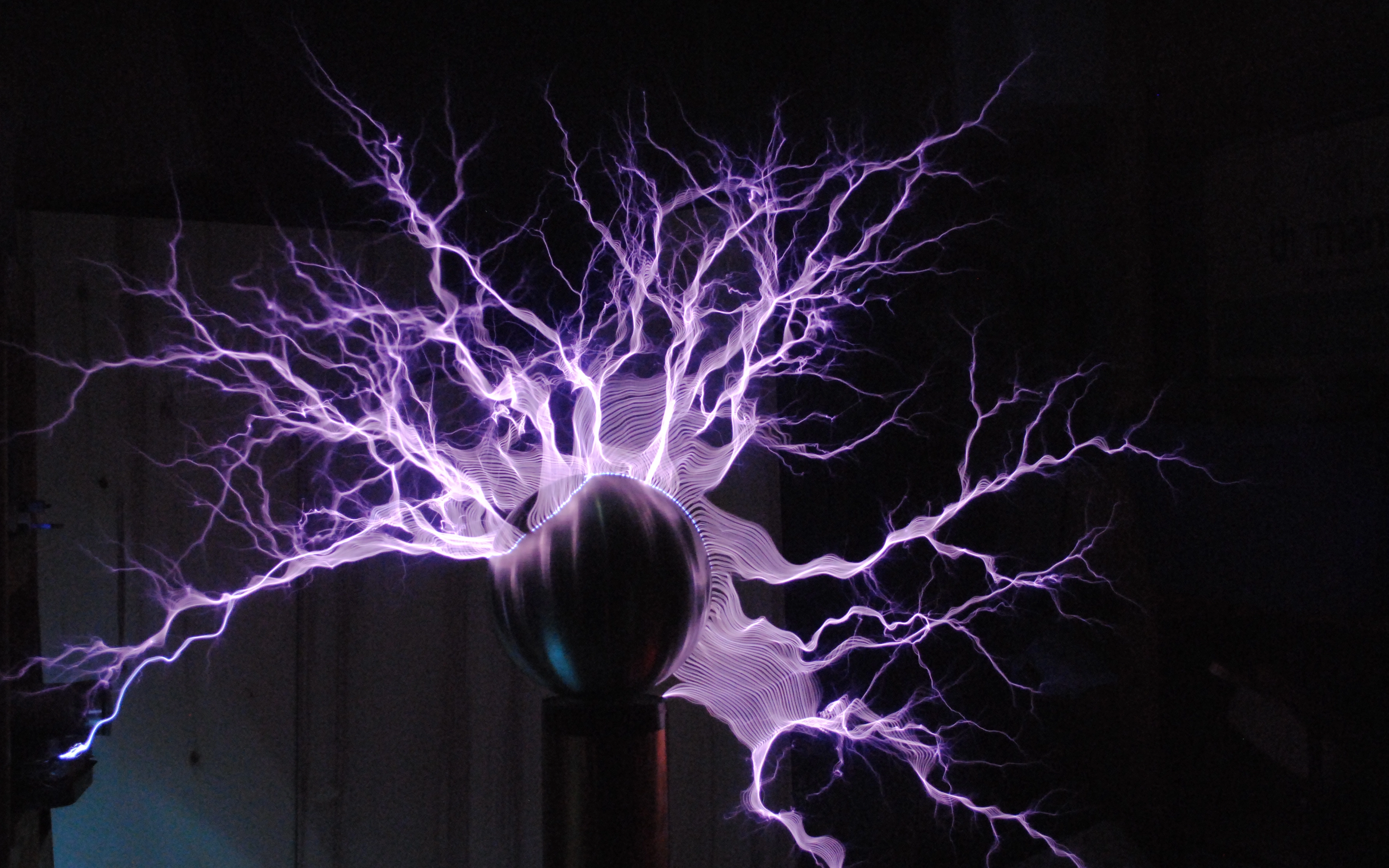
The coil in the middle was built in high school and the left coil a few years later. They both feature a neon sign transformer MMC based design with the small coil reaching roughly 0.8m and the big one 1.1m discharge length respectively.
A typical Tesla coil setup consists out of two loosely coupled resonant circuits. A relatively high capacitance and low inductance are used in the primary circuit. In contrast, the secondary circuit employs a low capacitance and large inductance. The secondary inductor is traditionally realized using a large air-core coil, which is the visually defining factor of a tesla coil. Exact frequency matching is required to avoid destructive interference between the two circuits, or, in other words, generate big sparks.
Energy is injected into the primary resonant circuit by pre-charging the capacitor. When the voltage across the capacitor terminals is sufficiently high, a spark gap will break down. The resistance of the spark gap drops drastically and it starts to conduct. The primary LC-circuit is closed and starts to oscillate. Energy is transferred to the secondary side. The voltage quickly rises until the surrounding air's breakdown voltage is reached. A loose coupling is important in air quenched designs, as to provide sufficient time for the spark gap to stop conducting once the primary voltage drops. While initial transfer is less efficient, further transfer cycles are avoided resulting in better overall efficiency.
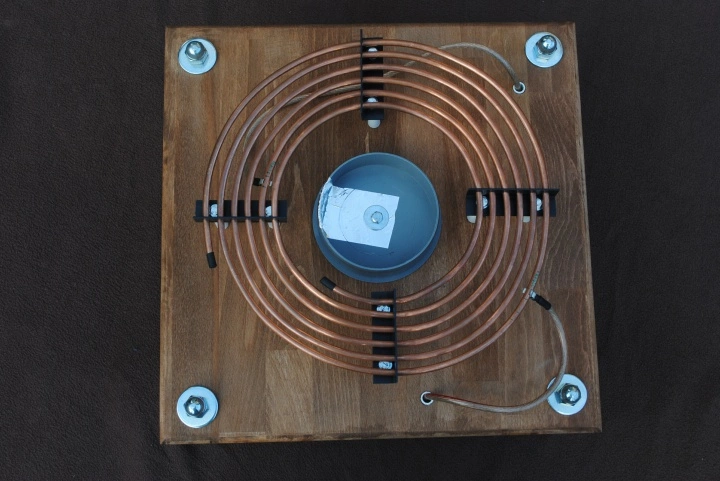
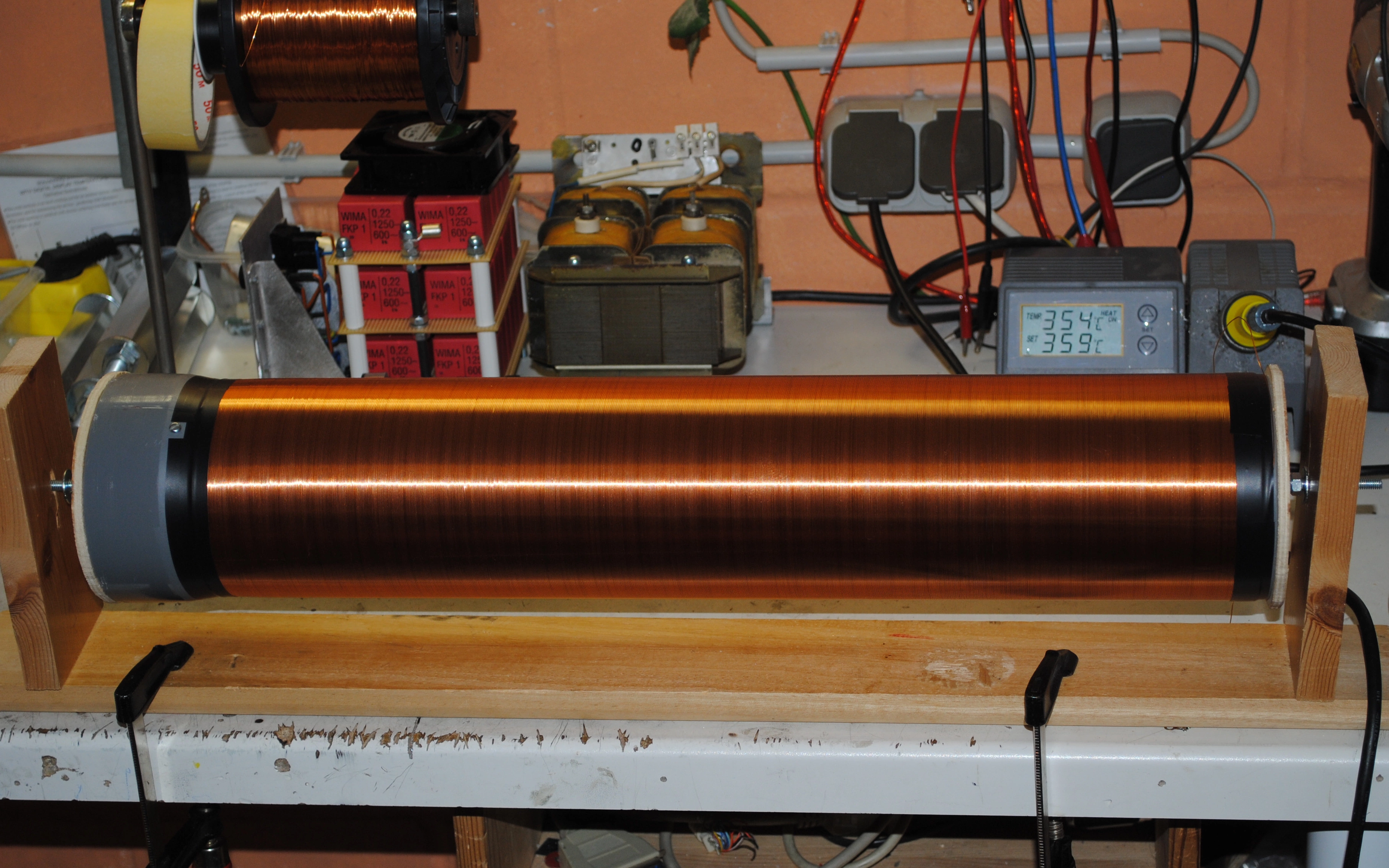
I have built most of my primary coils as flat spiral type design. The coil is supported using four spacers. The inductance was calculated using one of Wheeler's formulas. Primary coil taps are adjustable for tuning the primary LC-circuits resonant frequency. A flat inductor also ensures loose coupling between the resonant circuits. The secondary inductor was wound on a piece of sewage pipe. Since it has many turns, significant parasitic capacitance is formed that has to be considered for frequency matching. In case of the big coil, parasitic effects amount for roughly 20% of the total secondary capacitance. Medhurst's formula turned out to provide accurate estimates.
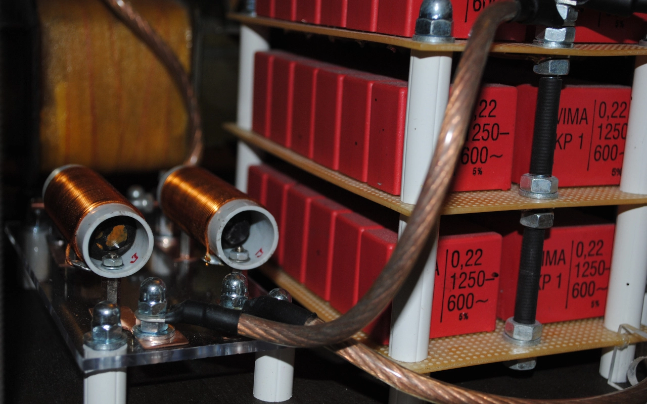
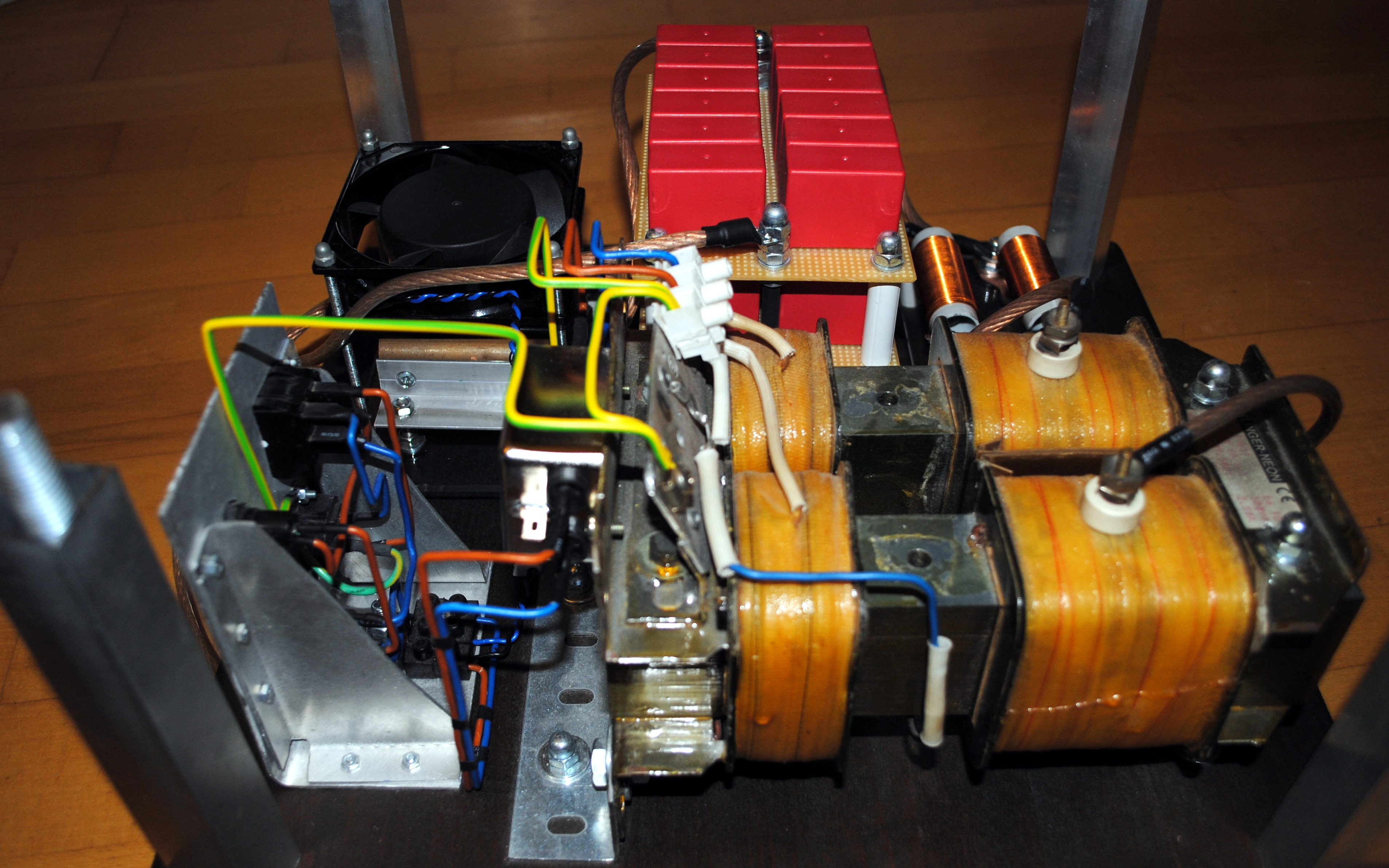
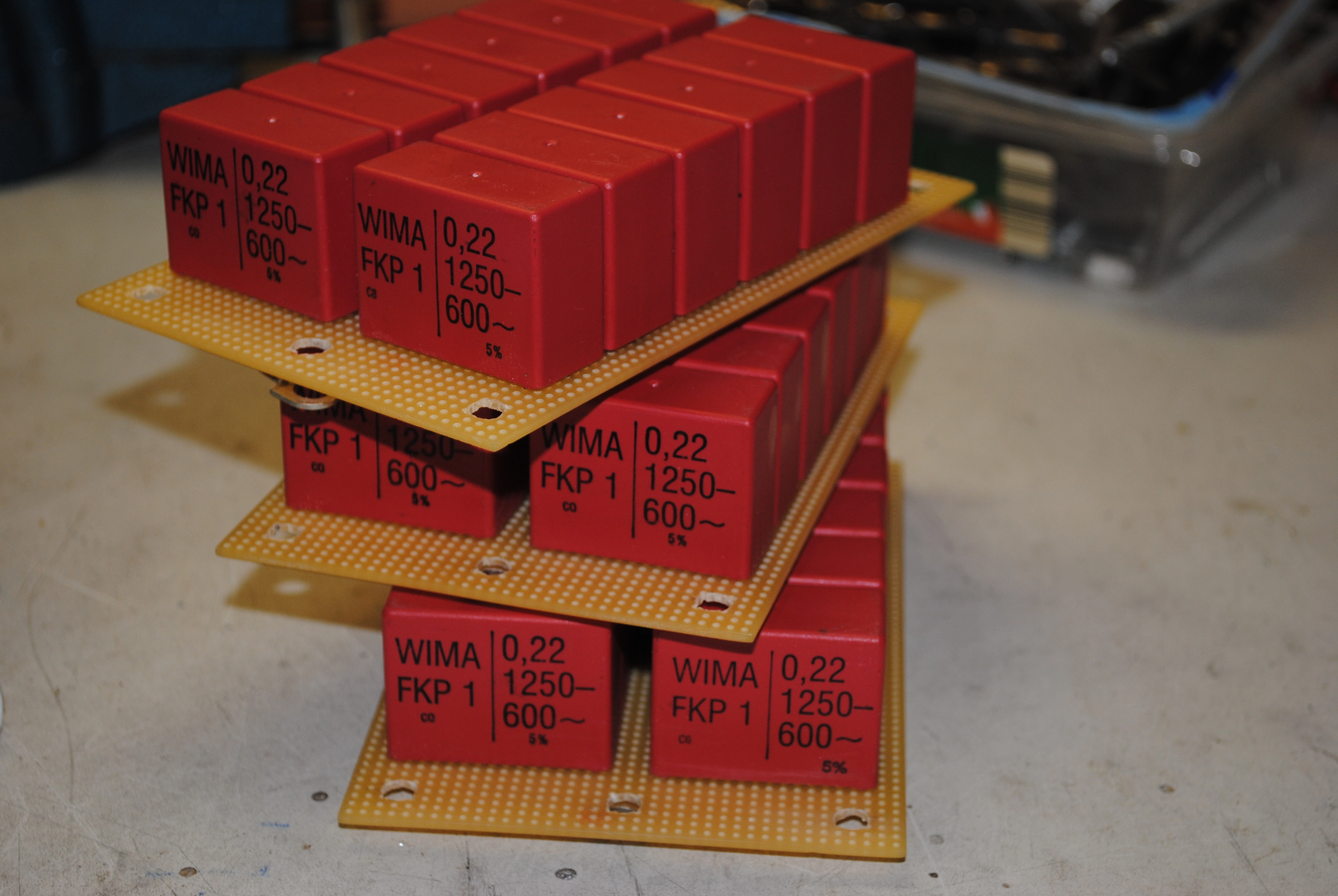
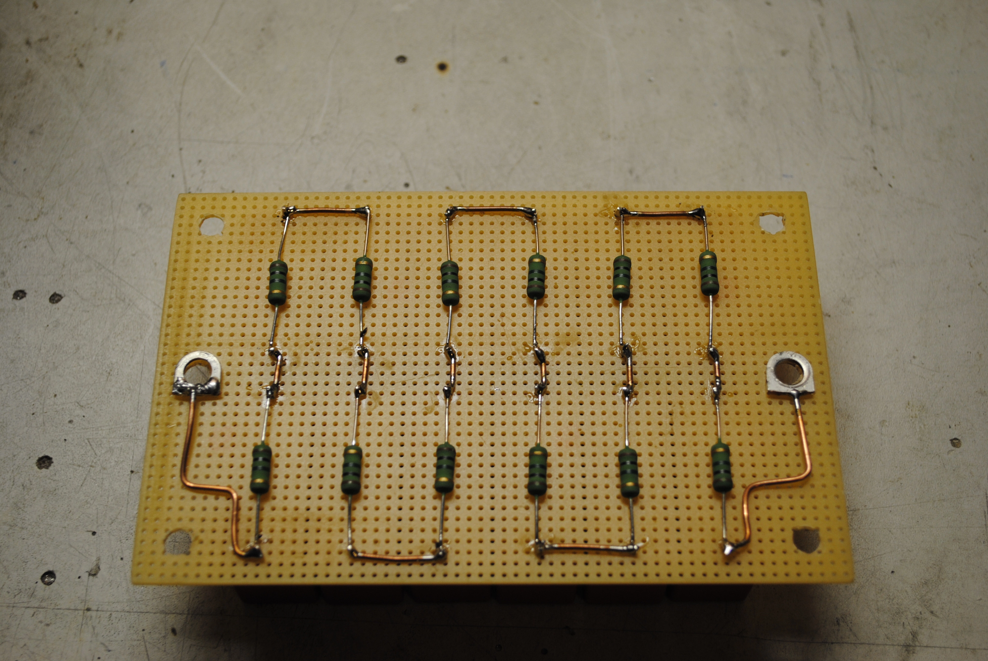
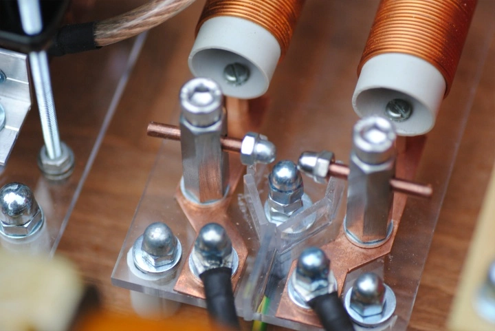
I have used Multi-Mini-Cap (MMC) designs in all my Tesla coils. Multiple small capacitors are connected in series to reach the required voltage rating. Several of these capacitor strings are then connected in parallel to match the required capacitance. A parallel resistor is connected to each capacitor for evening out the voltage distribution across the string and discharge any remaining partial charge after operation. The capacitors used must be properly sized for impulse loads or will blow up due to very high surge currents.
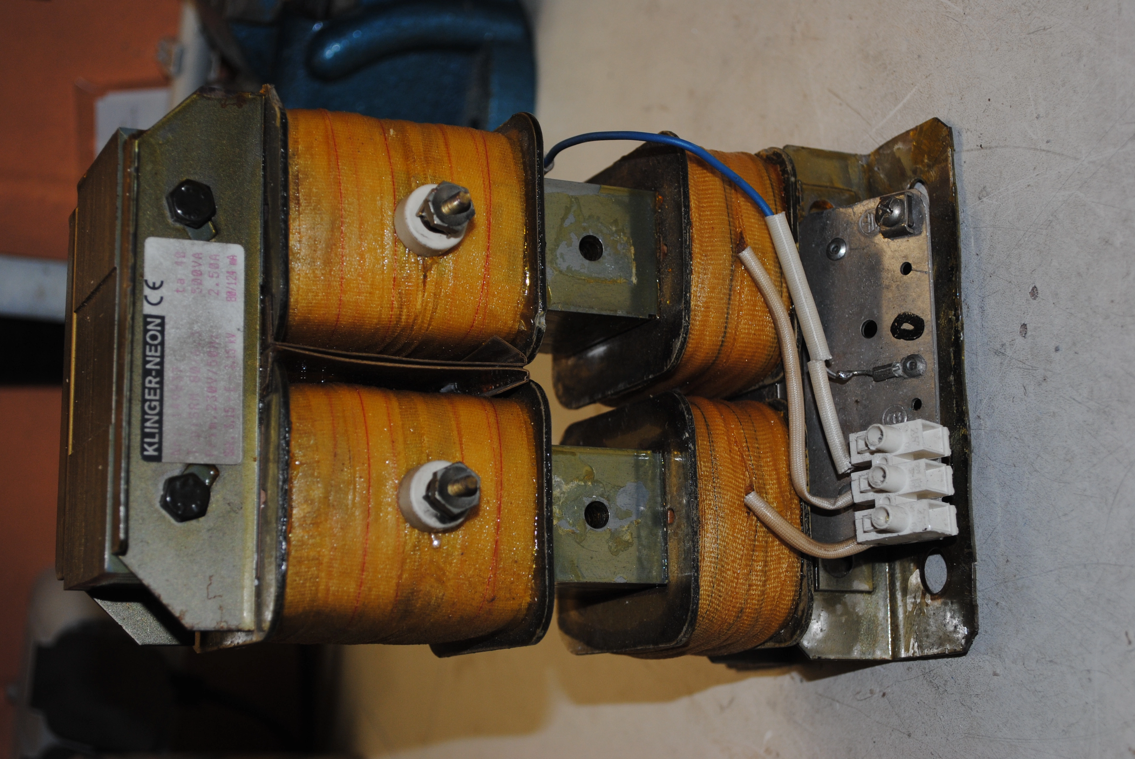
Typically spark gap tesla coil systems use a primary feed voltage between 5 and 10 Kilovolts. Because the resonance frequency of the LC-circuit is much higher than mains frequency, the capacitor can be connected directly to a mains transformer. The feed transformer needs to be appropriately sized to charge the capacitor such that the spark gap can conduct. I used neon sign transformers for my coils that I modified by removing the stray flux cores. Removing the transformer's intrinsic current limiting, this aproach allows for much higher power delivery, but comes at the cost of increased heat generation.
The spark gap was designed to provide constant air flow to aid fast quenching. Fast quenching is important for good coil performance as to avoid transfer of energy from the secondary circuit back to the primary side.